40G QSFP+ 10km PSM4 Transceivers
40G QSFP+ 10km PSM4 Transceivers
40G QSFP+ 10km PSM4 Transceivers
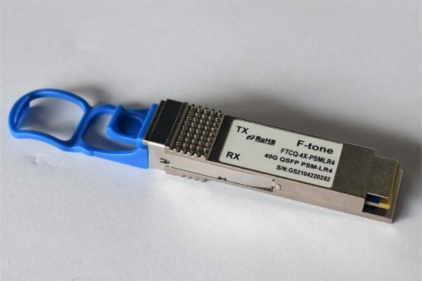
The FTCQ-4X-PSMLR4-GC&FTCQ-4X-PSMLR4I-GC QSFP+ PSM4 optical transceiver is intended for up to 10km reach service with four-lane 10.3125G data rate. It is based on 3.3V DC power supply and operates in the temperature range. It is compliant with QSFP MSA、SFF-8436 and IEEE802.3ba-2018. Digital diagnostic functions are available via I2C interface, and the control functions can be achieved by LVTTL interfaces on the host, mainly including Module Select(ModSelL)、Module Reset(ResetL)、Low Power Mode(LPMode). The transceiver incorporates a four-laser array which is usually DFB 、four-PIN diode array 、an integrated four drivers and TIAs IC separately. The differential AC coupled Tx and Rx data interfaces are CML compatible.
Applications
● 40G BASE Ethernet
● Infiniband EDR interconnects
● Enterprise networking
Features
● MPO-12 optical interface
● Maximum link length up to10km
● Up to 10.3125Gb/s data links per lane
● +3.3 V power supply
● QSFP MSA compliant package
● Hot Pluggable
● High performance singal mode DML transmitter
● High sensitivity PIN/TIA optical receiver
● Single Mode operation
● Case Operating temperature: 0 to 70ºC, -40to +85 ºC
● Data and Control Interfaces
● Tx Data CML/AC Coupled
● Rx Data CML/AC Coupled
● ModSelL LVTTL
● ResetL LVTTL
● ModPrsL LVTTL
● LPMode LVTTL
● 2-wire I2C communication bus
● RoHS 6 compliance
Absolute maximum parameters
Operating conditions
Electrical Characteristics
Optical Specification Note:
Note:
1. Even if the TDP < 0.8dB, the OMA min must exceed the minimum value specified here. Note:
Note:
1. The receiver shall be able to tolerate, without damage, continuous exposure to a modulated optical input signal having this power level on one lane. The receiver does not have to operate correctly at this input power.
2. Measured with conformance test signal at receiver input for BER = 1e-12 .
3. Vertical eye closure penalty and stressed eye jitter are test conditions for measuring stressed receiver sensitivity. They are not characteristics of the receiver.
PIN ASSIGNMENT
PIN DESCRIPTION
 Notes:
1、Tolerance: +/-0.1mm.
2、Others according to SFF-8661 or customer spec .
3、Optical port according to fiber connector spec.
Digital Diagnostic Monitor Accuracy
The following characteristics are defined over recommended operating conditions
Ordering Code
Important Notice
Performance figures, data and any illustrative material provided in this data sheet are typical and must be specifically confirmed in writing by F-tone Networks before they become applicable to any particular order or contract. In accordance with the F-tone Networks policy of continuous improvement specifications may change without notice.
The publication of information in this data sheet does not imply freedom from patent or other protective rights of F-tone Networks or others. Further details are available from any F-tone Networks sales representative.
Share

About F-tone Networks
F-tone Networks is now a world leader in development of optical transceivers and provide a wide range of high-speed optical solutions for optical communication networking, especially for AI, Data Center, enterprise data networking, Industry, aerospace, mining, shipbuilding, railway, metro, long haul transport networking, and mobile access networking applications
F-tone Networks invested in foundational photonics technologies and extensive product development and engineering with global presence in many area also.

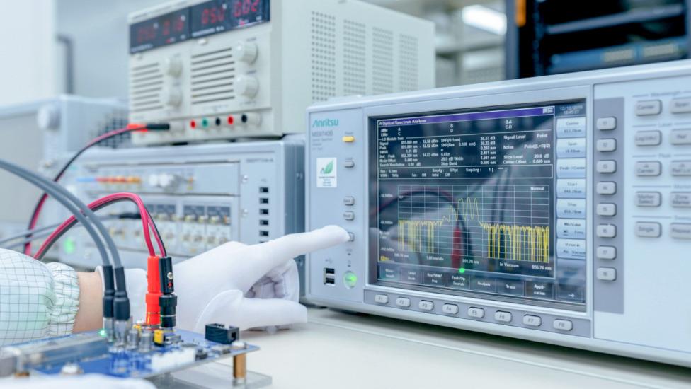
Power and Wavelength Testing
Test the signal delivering strength and wavelength, to ensure the signal decoding capacity of the receiver, and the wavelength remains consistent from the transmitter to the receiver.

Traffic Testing
Test the bit error rate and packet loss rate, to make them meet the corresponding standards and ensure the performance of transceivers.

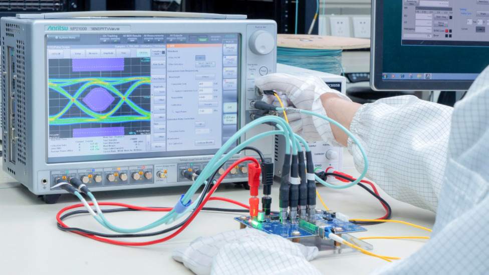
Optical Performance Testing
Test the transceivers' eye diagram situation, receiving sensitivity, extinction ratio, wavelength, light-emitting, light-receiving, current and voltage, to ensure the signal quality, stability and reliability of the transmission.

End Face Testing
Check the end face of the transceivers and keep them clean for more stable data transmission, better performance, and durability.

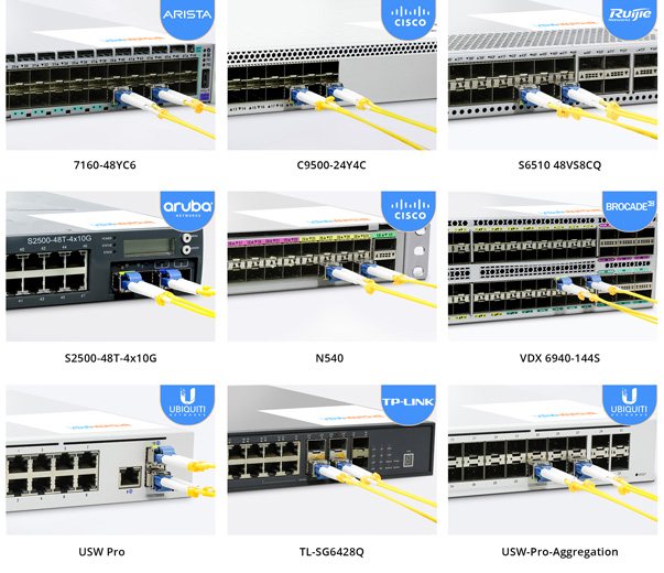
Various Switch Tests
Every module is quality tested for compatibility in the multi-brand switches environment, guaranteeing flawless operations.
Featured collection
-
AVAGO HFBR-2521ETZ Compatible Domestic Alternative Optical Module
Regular price $0.00Regular price -
AVAGO HFBR-1521ETZ Compatible Domestic Alternative Optical Module
Regular price $0.00Regular price -
AVAGO HFBR-1528Z Compatible Domestic Alternative Optical Module
Regular price $0.00Regular price -
AVAGO HFBR-2528Z Compatible Domestic Alternative Optical Module
Regular price $0.00Regular price


